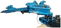
Hydraulic Mud-gun
PEIE Design, Engineering, Manufacture, Supply, Erection &  commissioning 2nd generation Mud-gun machine in TPM methodology with following customer delighting features. We control cost by work hard.
|
EXECUTIVE SUMMARY |
||
|
OBJECTIVES |
The intention of this supply is to achieve the minimum criteria for closing the tap-hole of Blast furnace after Hot metal/slag drain or draining condition. |
|
|
FEED MATERIAL |
Ramming Clay/Mug-gun mass, water or Tar bonded |
|
|
EQUIPMENT CAPACITY(Mud Holding Volume) |
60 LITER |
40 LITER |
|
FLOOR REQUIREMENT |
PEIE MUDGUN system 36 m2 without Hydraulic line length |
See detail Matrix |
|
WATER REQUIREMENT |
For cooling of oil at hydraulic oil into heat exchanger , In circuit 10 m3 /hr; Top‐up ~02 m3/hr |
Quality: Treated |
|
POWER REQUIREMENT |
30 KW max |
See detail list |
|
MAJOR EQUIPMENTS |
Mud-gun machine with accessories |
|
|
DELIVERY SCHEDULE |
14 weeks from date of Drawing approval |
|
|
SCOPE OF WORK |
|
|
GENERAL PROCESS DESCRIPTION
|
PROCESS |
|
|
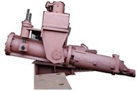
PEIE Mud-Gun consists of a Pedestal with a vertical column holding the swiveling Boom. |
Boom holds the Barrel Unit comprising of Nozzle, [Heat shielded] Barrel, Stroke Indicator, Hydraulic- Cylinders, |
|
Levers and other accessories. During closing, the Mud Gun is brought to tap hole, aligned and clamped by another Hydraulic Cylinder.. |
Then the mud pushed by actuating the pushing Cylinder. |
|
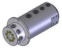
The Mud Gun assembled with Swivel Joint & Hose-less piping system. |
Power pack facilitates to operate the hydraulic actuators |
 The Boom swivels through a gear train operated by a Hydraulic Motor.
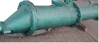
OPERATIONAL PARAMETERS
|
|
60 Liter |
40 Liter |
|
Swiveling Angle |
180 deg. (Normal)/270 deg. (Max.) |
Yes |
|
Swiveling Time |
5 – 10 sec [adjustable] |
Yes |
|
Plugging angle |
Adjustment lateral +/-20 , Horizontal & vertical +/- 250 |
Adjustment lateral +/-20 , Horizontal & vertical +/- 250 |
|
Adjustment |
lateral +/-20 , Horizontal & vertical +/- 250 |
lateral +/-20 , Horizontal & vertical +/- 250 |
|
Clay Pressure at Nozzle |
55 kg/cm2 |
40 kg/cm2 |
|
Mud Volume |
60 litre |
40 litre |
|
Type of Clay |
Water / Tar Bonded |
Water / Tar Bonded |
|
Holding Force |
5500 kg |
|
|
Injection Speed |
115 mm/sec [adjustable] |
|
|
Nozzle Tip Dia |
100 mm. |
|
|
Conical Nozzle Tip Diameter |
120 mm |
|
|
Barrel Size |
300 mm dia. x 850 mm |
|
TECHNICAL DETAILS / SPECIFICATION (HYDRAULIC COMPONENTS )
|
Hydraulic Power Pack |
|
|
a) Tank Material & Capacity b) Description of various Fittings c) Overall Dimension d) Oil Specification and Quantity e) Weight including Oil f) Cooling Water reqd, Qty & Pipe Size g) Make of Power Pack |
a) IS 2062 & 180 Gallon b) SW Fitting c) After detail engineering. d) Servo system HLP-68, 800 Lt. e) Later f) Details later g) Rexroth / Parkar |
|
Pump for Cylinder Operation |
|
|
a) Discharge b) Pressure: c) Flow: d) Make e) Motor Make & Rating (KW): |
a) Dual Delivery Vane [1 W + 1 S] b) 160 kg/cm2 c) 140 lpm d) Parker / Rexroth e) Siemens / ABB & 55 KW [Class F/B] |
|
Hydraulic Motor (Swivelling) |
|
|
a) Geometric Displacement: b) Geometric Torque: c) Inlet differential Pressure: d) Max. Speed: e) Operating Speed: f) Make: |
a) 42 cc/rev b) 7.02 NM/bar c) 293 bar d) 450 rpm e) 100 rpm f) Danfoss / Parker |
|
Hydraulic Cylinder [Mud Pushing] |
|
|
a) Bore Diameter b) Rod Diameter. c) Stroke : d) Type: e) Barrel Mounting. f) Piston Rod Mounting: g) Rod & rear end Port location h) Make: |
a) 200 mm b) 125 mm c) 850 mm d) Front Flange e) Front Flange f) Std. g) Horizontal upward h) ESS Hyd / Hydrocraft. |
|
Hydraulic Cylinder [Clamping] |
|
|
a) Bore Dia.: b) Rod Dia.: c) Stroke : d) Type: e) Barrel Mounting: f) Piston Rod Mounting : g) Rod & rear end Port location: h) Make: |
a) 125 mm b) 90 mm c) 400 mm d) Front Flange e) Std. f) Std. g) vertical upward i) ESS Hyd / eqvl. |
|
Flexible Hose Pipes: |
Hose-less piping system |
|
Material of construction |
|
|
a) Base Frame & Linkage: b) Body: c) Mud Barrel : d) Mud Barrel Tip : e) Weld Inspection: |
a) IS 2062 & MS/C45 b) IS 2062 c) Seamless Pipe d) Steel casing / s.s. e) DP [wherever necessary] |
|
ELECTRICALS |
|
|
a) Starter Panel
b) Control Console
c) Limit Switches |
|
|
PAINTING |
Heat Resistant Paint |
|
OPERATING STATION |
Control push button Operators’ Stations located at safe and visible place to the tap hole |
 commissioning 2nd generation Tap hole Drill machine in TPM methodology with following customer delighting features. We control cost by work hard.